In this blog, we’ll walk through how to set up a LoRaWAN end-device (node) using an ESP32 development board and an SX1276 LoRa transceiver. We’ll be using the MCCI LoRaWAN LMIC library v5.0.1 to implement OTAA (Over-The-Air Activation) and connect the node to ChirpStack.
📡 Hardware Requirements
- ESP32 DevKit (e.g., ESP32-WROOM-32)
- SX1276-based LoRa module (e.g., RFM95)
- Jumper wires
- Gateway connected to ChirpStack
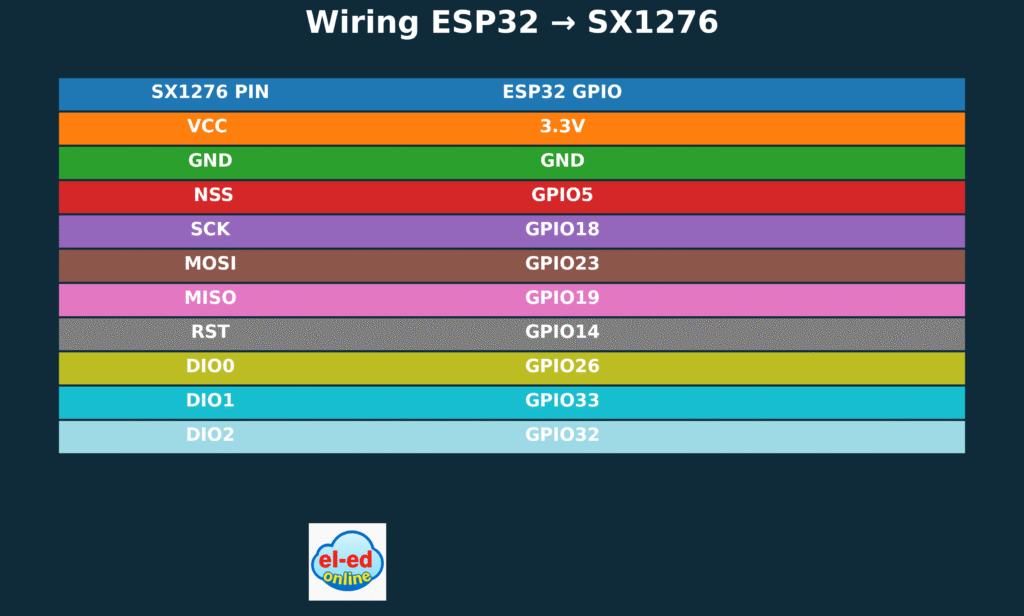
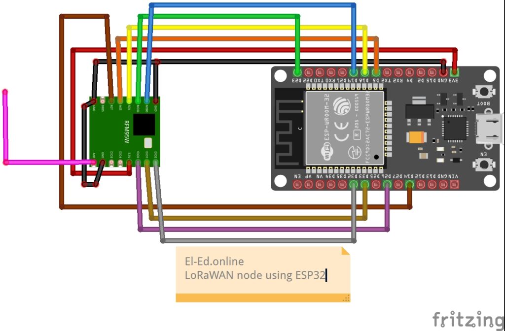
Wiring the ESP32 and SX1276 Module
⚙️ Software Requirements
- Arduino IDE (with ESP32 board support)
- MCCI LoRaWAN LMIC library v5.0.1
- ChirpStack Network + Application server
Programming the LoRa Node (OTAA Mode)
🔑 Step 1 – Define LoRaWAN credentials in the Arduino Code.
💻 Programming the LoRa Node (OTAA Mode)
We’re using the Over-The-Air Activation (OTAA) method to securely join the network.
In your Arduino sketch, define your keys as below:
void os_getDevEui (u1_t* buf) {
  uint8_t devEui[8] = { 0xCC, 0xBB, 0xAA, 0x00, 0x00, 0x00, 0x80, 0x00 };
  memcpy(buf, devEui, 8);
}

void os_getAppEui (u1_t* buf) {
  uint8_t appEui[8] = { 0x00, 0x00, 0x00, 0xD0, 0x7E, 0xD5, 0xB3, 0x70 };
  memcpy(buf, appEui, 8);
}

void os_getAppKey (u1_t* buf) {
  uint8_t appKey[16] = { 0x2B, 0x7E, 0x15, 0x16, 0x28, 0xAE, 0xD2, 0xA6,
                         0xAB, 0xF7, 0x15, 0x88, 0x09, 0xCF, 0x4F, 0x3C };
  memcpy(buf, appKey, 16);
}
🧭 Step 2 – Verify Region and Library
Edit your lmic_project_config.h:
which will be present in the folder mostly
\Documents\Arduino\libraries\MCCI_LoRaWAN_LMIC_library\project_config
The following is the specification we have tested for this node.
// project-specific definitions
//#define CFG_eu868 1
#define CFG_us915 1
//#define CFG_au915 1
//#define CFG_as923 1
// #define LMIC_COUNTRY_CODE LMIC_COUNTRY_CODE_JP      /* for as923-JP; also define CFG_as923 */
//#define CFG_kr920 1
//#define CFG_in866 1
#define CFG_sx1276_radio 1
//#define CFG_sx1261_radio 1
//#define CFG_sx1262_radio 1
//#define ARDUINO_heltec_wifi_lora_32_V3
//#define LMIC_USE_INTERRUPTSCopy the full code from below if needed, flash it to your ESP32 connected to the LoRa module.
/* OTAA example for ESP32 + SX1276 (MCCI LMIC v5.0.1)
   - Uses callback style required by v5.0.1:
         os_getDevEui(), os_getArtEui(), os_getDevKey()
   - Wiring (ESP32 DevKit):
       VCC  -> 3.3V
       GND  -> GND
       NSS  -> GPIO5   (.nss = 5)
       SCK  -> GPIO18
       MOSI -> GPIO23
       MISO -> GPIO19
       RST  -> GPIO14
       DIO0 -> GPIO26
       DIO1 -> GPIO33
       DIO2 -> GPIO32
*/

#include <lmic.h>
#include <hal/hal.h>
#include <SPI.h>

// -----------------
// *** IMPORTANT ***
// Replace the example arrays below with your ChirpStack values.
// See the "Byte order / how to paste" notes after the code.
// -----------------

// Example DevEUI (8 bytes) -- LITTLE-ENDIAN order (LSB first)
// If ChirpStack shows: 80B3D57ED005ABCD
// then in code (lsb first) it becomes: {0x34,0x12,0x05,0xD0,0x7E,0xD5,0xB3,0x70}
static const u1_t PROGMEM DEVEUI[8] = { 0xCD, 0xAB, 0x05, 0xD0, 0x7E, 0xD5, 0xB3, 0x80 };

// Example AppEUI / JoinEUI (8 bytes) -- LITTLE-ENDIAN (LSB first)
// If your JoinEUI is 0000000000000000 then lsb-first is all zeros too.
static const u1_t PROGMEM APPEUI[8] = { 0x00,0x00,0x00,0x00,0x00,0x00,0x00,0x00 };

// Example AppKey (16 bytes) -- BIG-ENDIAN (MSB first)
// If ChirpStack shows AppKey: 2B7E151628AED2A6ABF7158809CF1234
// paste exactly as shown (msb first)
static const u1_t PROGMEM APPKEY[16] = {
  0x2B,0x7E,0x15,0x16,0x28,0xAE,0xD2,0xA6,
  0xAB,0xF7,0x15,0x88,0x09,0xCF,0x12,0x34
};

// -----------------
// v5.0.1 requires these callbacks to supply OTAA credentials
void os_getArtEui (u1_t* buf) { memcpy_P(buf, APPEUI, 8); }  // AppEUI / JoinEUI (lsb)
void os_getDevEui (u1_t* buf) { memcpy_P(buf, DEVEUI, 8); }  // DevEUI (lsb)
void os_getDevKey (u1_t* buf) { memcpy_P(buf, APPKEY, 16); } // AppKey (msb)

// -----------------
// Pin mapping for ESP32 DevKit + RFM95
const lmic_pinmap lmic_pins = {
  .nss = 5,               // CS
  .rxtx = LMIC_UNUSED_PIN,
  .rst = 14,              // RST
  .dio = {26, 33, 32}     // DIO0, DIO1, DIO2
};

static osjob_t sendjob;
const unsigned TX_INTERVAL = 60; // seconds between uplinks after join completes
static uint16_t seqno = 0;

void do_send(osjob_t* j);

// LMIC event handler
void onEvent (ev_t ev) {
  Serial.print(os_getTime());
  Serial.print(": ");
  switch(ev) {
    case EV_JOINING:     Serial.println(F("EV_JOINING")); break;
    case EV_JOINED:
      Serial.println(F("EV_JOINED"));
      LMIC_setLinkCheckMode(0); // disable link check (optional)
      os_setTimedCallback(&sendjob, os_getTime() + sec2osticks(5), do_send);
      break;
    case EV_JOIN_FAILED: Serial.println(F("EV_JOIN_FAILED")); break;
    case EV_REJOIN_FAILED: Serial.println(F("EV_REJOIN_FAILED")); break;
    case EV_TXCOMPLETE:
      Serial.println(F("EV_TXCOMPLETE"));
      if (LMIC.dataLen) {
        Serial.print(F("Downlink, "));
        Serial.print(LMIC.dataLen);
        Serial.println(F(" bytes"));
      }
      // schedule next send
      os_setTimedCallback(&sendjob, os_getTime() + sec2osticks(TX_INTERVAL), do_send);
      break;
    default:
      Serial.print(F("Event: "));
      Serial.println((unsigned)ev);
      break;
  }
}

void do_send(osjob_t* j) {
  if (LMIC.opmode & OP_TXRXPEND) {
    Serial.println(F("OP_TXRXPEND, not sending"));
    return;
  }
  uint8_t payload[2];
  payload[0] = (seqno >> 8) & 0xFF;
  payload[1] = seqno & 0xFF;
  Serial.print(F("Queueing TX seq="));
  Serial.println(seqno);
  LMIC_setTxData2(1, payload, sizeof(payload), 0);
  seqno++;
}

void setup() {
  Serial.begin(115200);
  while (!Serial) delay(10);
  Serial.println(F("\nESP32 OTAA (MCCI LMIC v5.0.1) example"));

  // LMIC init
  os_init();
  LMIC_reset();
  #if defined(CFG_us915)
  // Use sub-band 1 (channels 8–15), typical for TTN/ChirpStack gateways
  LMIC_selectSubBand(1);
#endif

  // Set data rate & tx power (adjust for your region if needed)
  LMIC_setDrTxpow(DR_SF7, 14);

  // Start join
  LMIC_startJoining();
}

void loop() {
  os_runloop_once();
}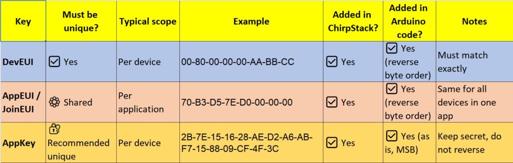
✅ Tip:
- DevEUI and AppEUI must be in LSB format (reverse order from ChirpStack).
- AppKey stays in MSB format (as shown in ChirpStack).
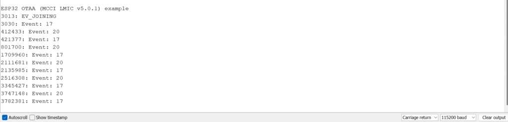
First Start without registering on Chirpstack.
On First start without registering the node on the chirpstack the serial monitor will look like this.